
Ground support and rock bolt mapping
Ground support is specified in a standard — bolt spacing, mesh overlap, shotcrete thickness — and installed by a crew at the face at the end of a cycle. Whether the installation matches the standard is checked by looking, and the record is a tick on a sheet.
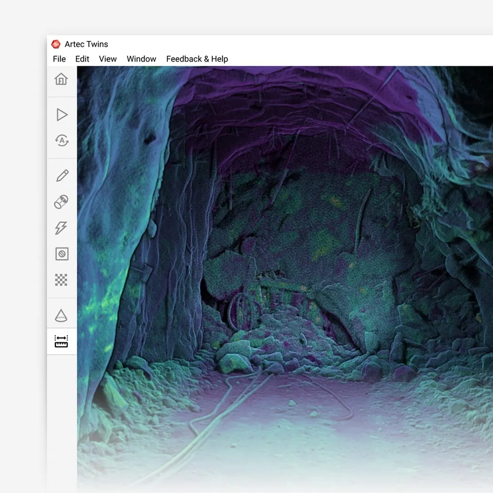
A scan of the supported drive records every bolt plate, the mesh and the shotcrete where they actually are, so the pattern is checked against the standard as a measurement and the as-installed support becomes part of the mine model.
Can installed ground support be mapped from a 3D scan?
Yes — bolt plates, mesh coverage and shotcrete extent are recorded at ±10 mm in the scan of the drive, checked against the standard and kept as a dated record.
 Pattern against standardBolt spacing and ring positions measured, not eyeballed.
 Coverage seen wholeMesh overlap, gaps and shotcrete extent across the back and walls.
 A dated QA recordThe support as installed, kept with the drive it is in.
 Later changeRe-scanned, the same section shows loaded plates, bagged mesh and cracked shotcrete.
Why the support record is a tick box
Ground support QA is visual. After the bolting crew has finished, someone looks at the round, judges the bolt spacing against the pattern in the standard, checks that the mesh overlaps and that the shotcrete looks thick enough, and signs the sheet. The bolts are hidden behind their plates, the spacing is estimated by eye, and the record says the round was supported to standard. If a section later fails, the question of whether it was supported as specified is answered from that sheet.
The gap between the standard and the installation is where the risk sits. A bolt ring installed 30 cm too far from the last, a mesh sheet that stops short of the shoulder, a shotcrete layer that thins over a wet patch — none of these is visible on a tick sheet, and each is exactly the kind of variation that ground support standards exist to prevent.
A scanned drive records the support as installed. Artec Jet captures the round after bolting at ±10 mm; every plate, the mesh and the shotcrete surface are in the model where they are. Bolt spacing and ring positions are measured against the standard, mesh coverage is seen whole, and shotcrete extent is mapped — with the pre-shotcrete scan, its thickness. The record is a dated surface kept with the drive, and a later re-scan shows plates that have loaded or mesh that has bagged.
From bolting to a measured QA record
The scan is taken in the same window as the visual check it replaces.
 1. Scan after boltingJet records the supported round at ±10 mm — plates, mesh and rock — as the drive is walked.
 2. RegisterTwins ties the capture to mine grid and to the previous pick-up of the same round.
- 3. Check the patternBolt plate positions against the standard’s spacing and ring layout; mesh overlap and gaps mapped.
 4. Shotcrete thicknessThe shotcrete surface against the bare-rock scan gives thickness across the section, thin spots coloured.
- 5. File the recordThe as-installed support into the mine model as the QA record for that round, with its date.
Which scanner for this work
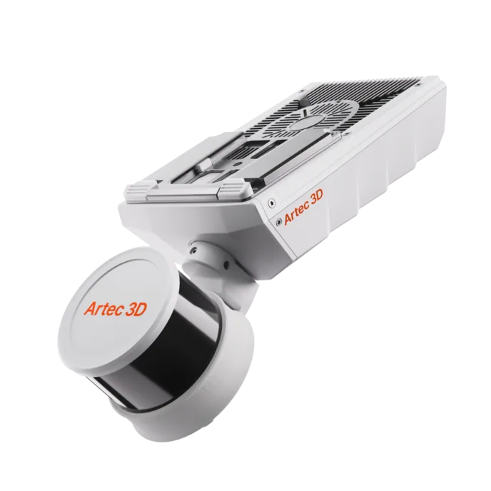
The support is mapped from the heading survey; a handheld scanner adds detail on a specific element when it matters.
Artec Jet
- Best for
- The supported drive as installed — plates, mesh and shotcrete at ±10 mm
- Type
- Multi-modal SLAM LiDAR
- Accuracy, up to
- ±10 mm underground, ±15 mm general
- Change detection
- ±5 mm
- Range
- 0.5–300 m
- Positional drift
- ±0.03%
- Deployment
- Handheld, backpack, pole, drone, vehicle, cage, robot
Jet records the round after bolting in the same walk-through that surveys it, so the support QA costs no extra time at the face. Its 360° × 290° field of view takes in the back and both walls together, which is where pattern and coverage are judged, and ±5 mm change detection between visits shows plates and mesh that have moved.
Artec Leo
- Best for
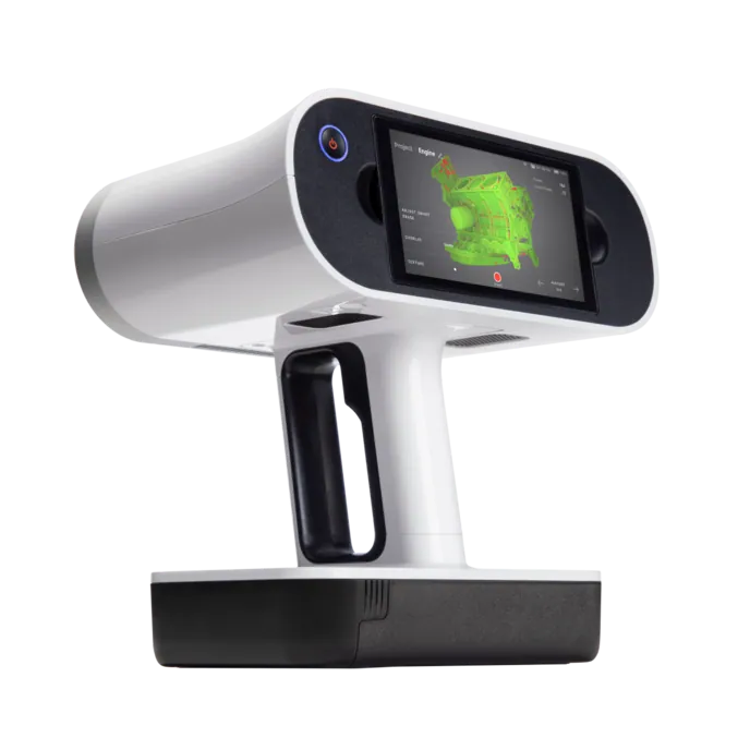
- A single plate, bolt head or shotcrete defect at 0.1 mm
- Type
- Wireless handheld structured light, all-in-one
- 3D point accuracy, up to
- 0.1 mm
- 3D resolution, up to
- 0.2 mm
- Working distance
- 0.35–1.2 m
- Capture speed
- Up to 35,000,000 points/s in HD Mode
- Onboard
- 5.5″ touchscreen, processing and 512 GB — no laptop
Where one element has to be examined — a plate that appears loaded, a crack in shotcrete, a bolt head for a pull-test record — Leo records it at 0.1 mm with colour texture, wirelessly, with its screen onboard. The detail registers into the Jet capture so it sits in the drive record.
See a bolted round checked against the support standard as a measurement, with mesh coverage and shotcrete thickness mapped — book a demo for your ground control engineer.
Book a demoQuestions ground control engineers ask
Can the scanner see the bolts?
It records the plates and bolt heads, which is what positions the pattern; the bolt itself is in the rock. Ring positions and spacing are measured from the plates against the standard.
How is shotcrete thickness measured?
From two scans: the bare rock before spraying and the shotcrete surface after. The difference, at ±10 mm on each surface, gives the thickness across the section with thin areas coloured.
Does this replace the QA sign-off?
It gives the sign-off a measured record. The standard is still the standard and the engineer still approves the round; what changes is that the approval rests on measured spacing and coverage rather than on a look.
What happens to the record later?
It stays with the drive in the mine model, dated. A later re-scan of the same section shows loaded plates, bagged mesh or cracked shotcrete as change against it, which is how support performance becomes a measurement.
Related applications

Tell us about your ground support QA
Describe the support standard, the ground and how installation is checked today. A mining specialist will come back with what a scanned round would record and how it fits the QA process.