
Raise and ventilation shaft scanning
A raise is signed off against a profile, a diameter and a verticality nobody has actually measured along its length. The as-built is the contractor’s reamer diameter and two survey points, one at each end.
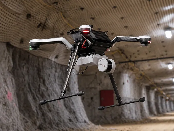
A scanner lowered from the collar or flown from the bottom records the whole opening as a surface, so the as-built, the airflow area and the condition of the walls are measured rather than assumed.
Can a raise or ventilation shaft be surveyed without entering it?
Yes — lowered from the collar or flown from the bottom, a SLAM LiDAR scanner records the full profile at ±10 mm: diameter, verticality and wall condition.
 As-built at every metreDiameter, cross-section area and profile along the full length, not at two ends.
 Verticality measuredThe axis of the opening against design, with deviation as a number per metre.
 Walls recordedLoose, overbreak and water inflow shown where they are, with depth.
 Nobody in the raiseFrom the collar or the bottom; no person enters the opening.
Why the as-built of a raise is mostly assumed
Raise boring and drop raising produce openings that nobody walks. The as-built record is what the method predicts: the reamer diameter, the pilot hole survey, a collar coordinate and a breakthrough coordinate. Whether the wall actually holds that diameter along its length — whether it overbroke in a weak band, whether there is a ledge where the ground changed — is inferred from the muck volume and the drilling records rather than measured.
A ventilation shaft is signed off on the airflow area it provides, and airflow depends on the actual cross-section, not the nominal one. A raise that overbroke carries more air than planned; one with a ledge or a hang-up carries less. Verticality matters for anything that is later installed in the opening — a ladderway, a pipe column, services — and a deviation found at installation is expensive to accommodate.
A scanner along the opening replaces the assumption with a surface. Artec Jet is lowered from the collar or flown from the bottom, holding ±0.03% positional drift with no GPS and recording the walls at ±10 mm in the dark. Artec Twins ties the capture to the collar and breakthrough coordinates and returns a cross-section at every metre: diameter, area, verticality against design, and the condition of the walls where the ground was weak.
From collar to as-built
One traverse of the opening gives every section along it.
 1. Rig at either endJet on a line from the collar, or on a drone at the bottom, with the opening clear.
 2. Traverse and captureThe full length at up to 1.9 million points per second with a 360° × 290° view, in complete darkness.
 3. Tie to mine gridTwins registers the capture to the collar and breakthrough coordinates so the axis sits in mine grid.
- 4. Section every metreDiameter, area and centreline at each metre; deviation from design plotted along the length.
 5. Hand over the as-builtPoint cloud and sections into the mine model and the ventilation model as LAS, LAZ or E57.
Which scanner for this work
The opening is vertical, unlit and unentered, which decides the device.
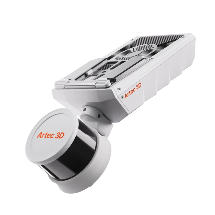
Artec Jet
- Best for
- The raise itself — lowered on a line or flown from the bottom
- Type
- Multi-modal SLAM LiDAR
- Accuracy, up to
- ±10 mm underground, ±15 mm general
- Change detection
- ±5 mm
- Range
- 0.5–300 m
- Positional drift
- ±0.03%
- Deployment
- Handheld, backpack, pole, drone, vehicle, cage, robot
At 1.57 kg and IP65, Jet is the scanner that can be sent down a raise on a line or flown up a ventilation shaft on a drone. Its ±0.03% drift keeps a long opening true with no GPS, its own light records walls in complete darkness, and the result is a cross-section at every metre at ±10 mm.
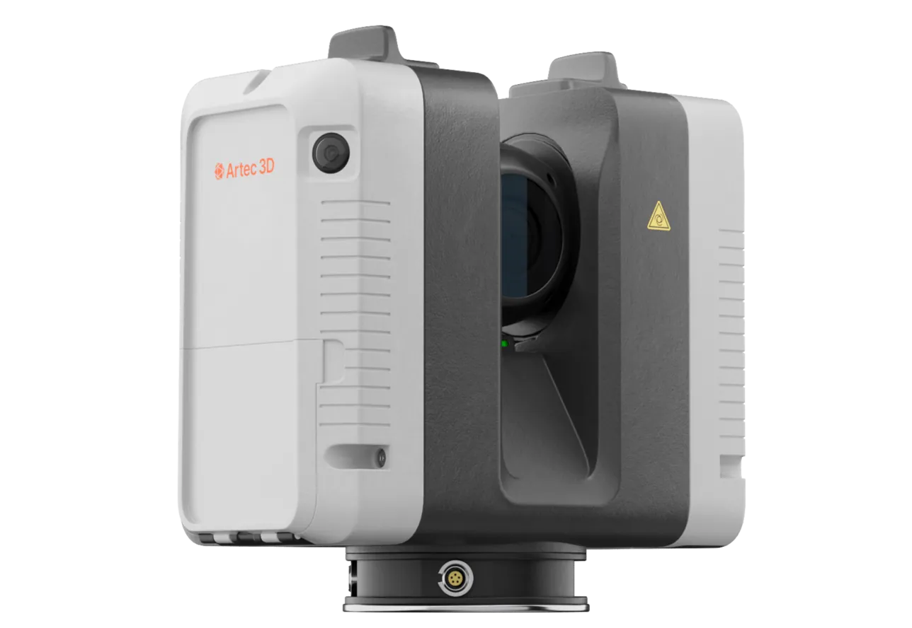
Artec Ray II
- Best for
- The collar, the breakthrough and the visible length of the raise from either end
- Type
- Stationary long-range laser, tripod mounted
- Accuracy, up to
- 1.9 mm at 10 m, 2.9 mm at 20 m, 5.3 mm at 40 m
- Range noise
- 0.4 mm at 10 m
- Range
- 0.5–130 m
- Scan time
- 1 min 42 s at 3 mm, 10 m, without texture
- Field of view
- 360° × 300°
Ray II on a tripod at the collar or the bottom records the raise as far as line of sight allows at 1.9 mm at 10 m, and fixes the collar and breakthrough geometry at survey-grade. On a short raise that may be the whole opening; on a long one it is the frame the Jet traverse is tied to.
See a raise turned into an as-built with a section at every metre and its verticality plotted against design — book a demo for your development team.
Book a demoQuestions surveyors ask
Can it survey a raise while the raise borer is still on site?
The scan needs the opening clear along the section being recorded. Immediately after breakthrough, before the reamer is stripped, is a common window; the collar and breakthrough coordinates from survey tie the capture to mine grid.
How is verticality measured?
From the centreline of the cross-sections along the opening. Each metre gives a centre; the run of centres against the design axis gives deviation per metre and total, in mine grid.
Does the airflow area come from the scan?
Yes. The cross-section area at every metre is measured from the wall surface, so the ventilation model works from the actual opening rather than the nominal reamer diameter.
What about a ladderway or services already installed?
They are recorded as part of the capture, at ±10 mm, in their true position. That is useful in itself: the as-built of what is in the raise, not just the raise.
Related applications
Tell us about the raises you sign off
Describe the method, the diameters and lengths, and what the as-built has to show. A mining specialist will come back with how the scanner is deployed and what one traverse returns.